How I Used AI To Recreate The Iconic Structure in King’s Cross Station With A Revit Macro
For years, the standard way to create complex, parametric geometry in Revit has been Dynamo. If you wanted a diagrid, a twisting tower, or a mathematical surface, you opened the visual programming interface and started wiring nodes.
But recently, I’ve been testing a different theory: Is AI + C# Macros actually faster and more efficient than Dynamo?
To test this, I decided to tackle one of the most geometrically complex structures in London: The Western Concourse roof at King’s Cross Station. I used an AI (Google Gemini) as my “Computational Lead,” challenging it to write a raw C# macro to generate the structure inside Revit 2024.
Here is how the experiment went down.
The Subject: An Architectural & Engineering Marvel
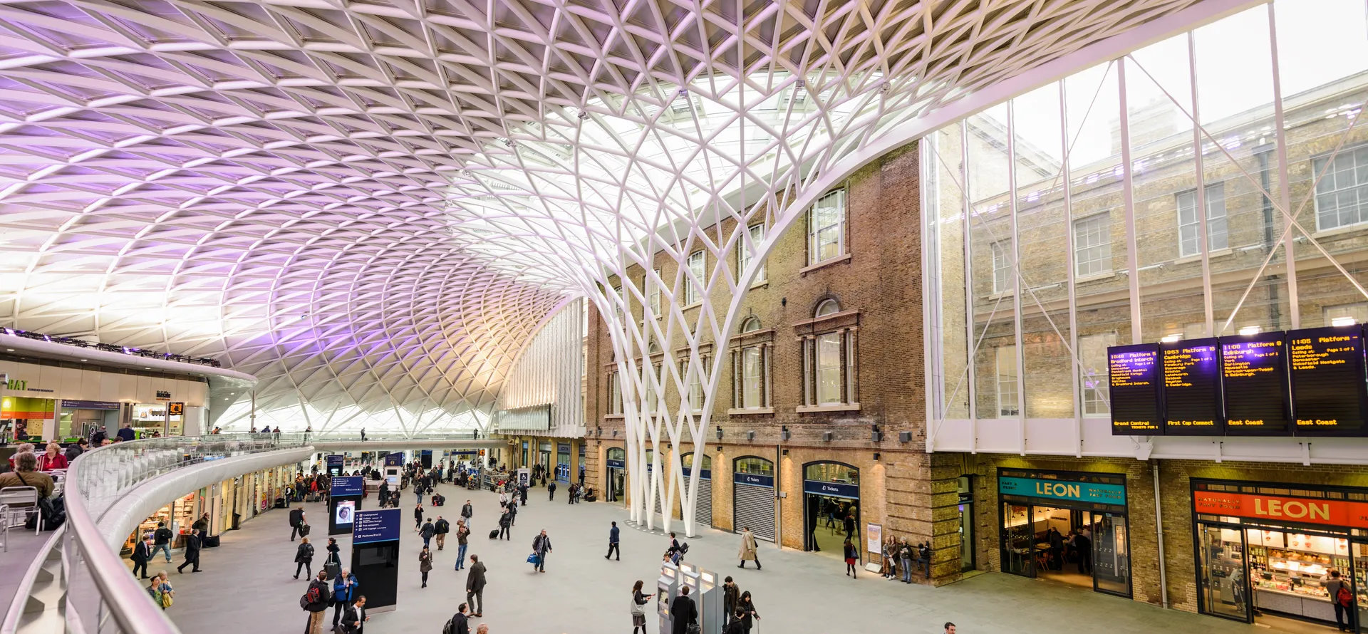
Before we dive into the code, we have to respect the geometry we are trying to mimic. The Western Concourse at King’s Cross, designed by John McAslan + Partners with engineering by Arup, is a stunning feat of modern construction.
It is essentially a “reverse waterfall”, a semi-circular steel diagrid that rises from a massive central funnel and peels out over the heads of commuters. The geometry is incredibly specific: a toroidal shape that transitions from a tight vertical trunk into a wide, swooping canopy. It was designed to span 150 meters without touching the historic Victorian station buildings and to funnel massive structural loads into a tiny footprint to avoid the subway tunnels below.
It is exactly the kind of complex design that usually requires hours of wiring up “spaghetti” node graphs in Dynamo.
The Challenge
My hypothesis was simple: I can get to the final geometry faster by asking an AI to write a C# macro than I can by building a Dynamo graph from scratch.
I gave the AI a single prompt:
“Are you familiar with the structure at King’s Crossing in London? The giant web of beams and trusses… Would it be possible for you to code a Revit 2024 macro in C# that builds that structure using Revit families?”
Gemini’s answer was a bit longwinded (as LLMs tend to be), but to sum it all up, the answer was a solid “yes.”
Let’s break it down.
Step 1: The Ingredients
The AI correctly identified that standard framing wouldn’t work for the curvature. It suggested using Adaptive Components.
Before running the script, I had to create a single “bone” for the structure. I built a simple 2-Point Adaptive Component (a cylinder connecting two adaptive points) and named it AC_Strut.rfa:
AC_Strut.rfa (95 downloads )Step 2: The Logic
Instead of dragging 50 nodes onto a canvas to calculate lists of points, vectors, and UV grids, the AI generated a clean C# loop.
The logic it used was surprisingly elegant:
- Define a grid of points on a curve.
- Use a math function (
t * t) to create the “trumpet” flare of the funnel. - Loop through the grid and place the
AC_Strutfamily diagonally to create the diamond lattice.
/*
 * Created by SharpDevelop.
 * User: jmerlan
 * Date: 1/22/2026
 * Time: 2:10 PM
 */
using System;
using Autodesk.Revit.UI;
using Autodesk.Revit.DB;
using Autodesk.Revit.UI.Selection;
using System.Collections.Generic;
using System.Linq;

namespace KingsCrossMacros
{
    [Autodesk.Revit.Attributes.Transaction(Autodesk.Revit.Attributes.TransactionMode.Manual)]
    [Autodesk.Revit.DB.Macros.AddInId("39F8ACAB-31D3-444C-9E04-C172EBA9979C")]
    public partial class ThisDocument
    {
        private void Module_Startup(object sender, EventArgs e)
        {
        }

        private void Module_Shutdown(object sender, EventArgs e)
        {
        }

        #region Revit Macros generated code
        private void InternalStartup()
        {
            this.Startup += new System.EventHandler(Module_Startup);
            this.Shutdown += new System.EventHandler(Module_Shutdown);
        }
        #endregion

        public void BuildRoofStructure()
        {
            Document doc = this.Document;

            // 1. SETTINGS
            string familyName = "AC_Strut";
            int uSegments = 20;
            int vSegments = 12;

            double trunkRadius = 15.0;
            double topRadius = 120.0;
            double height = 65.0;

            // 2. FIND THE FAMILY SYMBOL
            FamilySymbol symbol = new FilteredElementCollector(doc)
                .OfClass(typeof(FamilySymbol))
                .OfCategory(BuiltInCategory.OST_GenericModel)
                .Cast<FamilySymbol>()
                .FirstOrDefault(q => q.Name == familyName);

            // Error check
            if (symbol == null)
            {
                // FIX: Removed '$' and used concatenation instead
                TaskDialog.Show("Error", "Family '" + familyName + "' not found. Please load a 2-point Adaptive Component with this name.");
                return;
            }

            // 3. GENERATE GEOMETRY POINTS
            XYZ[,] gridPoints = new XYZ[uSegments + 1, vSegments + 1];

            for (int u = 0; u <= uSegments; u++)
            {
                double theta = (Math.PI * u) / uSegments;

                for (int v = 0; v <= vSegments; v++)
                {
                    double t = (double)v / vSegments;

                    // FUNNEL MATH:
                    double currentRadius = trunkRadius + (topRadius - trunkRadius) * (t * t);
                    double currentZ = height * t;

                    double x = currentRadius * Math.Cos(theta);
                    double y = currentRadius * Math.Sin(theta);

                    gridPoints[u, v] = new XYZ(x, y, currentZ);
                }
            }

            // 4. PLACE COMPONENTS (TRANSACTION)
            using (Transaction trans = new Transaction(doc, "Build King's Cross Roof"))
            {
                trans.Start();

                if (!symbol.IsActive) symbol.Activate();

                for (int u = 0; u < uSegments; u++)
                {
                    for (int v = 0; v < vSegments; v++)
                    {
                        XYZ p1 = gridPoints[u, v];
                        XYZ p2 = gridPoints[u + 1, v];
                        XYZ p3 = gridPoints[u, v + 1];
                        XYZ p4 = gridPoints[u + 1, v + 1];

                        // Place Diagonals
                        CreateAdaptiveComponent(doc, symbol, p1, p4);
                        CreateAdaptiveComponent(doc, symbol, p2, p3);
                    }
                }

                trans.Commit();
            }
        }

        private void CreateAdaptiveComponent(Document doc, FamilySymbol symbol, XYZ pStart, XYZ pEnd)
        {
            try
            {
                FamilyInstance instance = AdaptiveComponentInstanceUtils.CreateAdaptiveComponentInstance(doc, symbol);
                IList<ElementId> placePointIds = AdaptiveComponentInstanceUtils.GetInstancePlacementPointElementRefIds(instance);

                if (placePointIds.Count < 2) return;

                ReferencePoint point1 = doc.GetElement(placePointIds[0]) as ReferencePoint;
                point1.Position = pStart;

                ReferencePoint point2 = doc.GetElement(placePointIds[1]) as ReferencePoint;
                point2.Position = pEnd;
            }
            catch (Exception ex)
            {
                // Ignore errors to keep loop running
            }
        }
    }
}
Step 3. The Result
Once I ran the macro, the complete diagrid structure appeared in the viewport after 11.02 seconds — much faster that I anticipated.
Below is a 3D view of what AI was able to create using a C# macro in Revit:
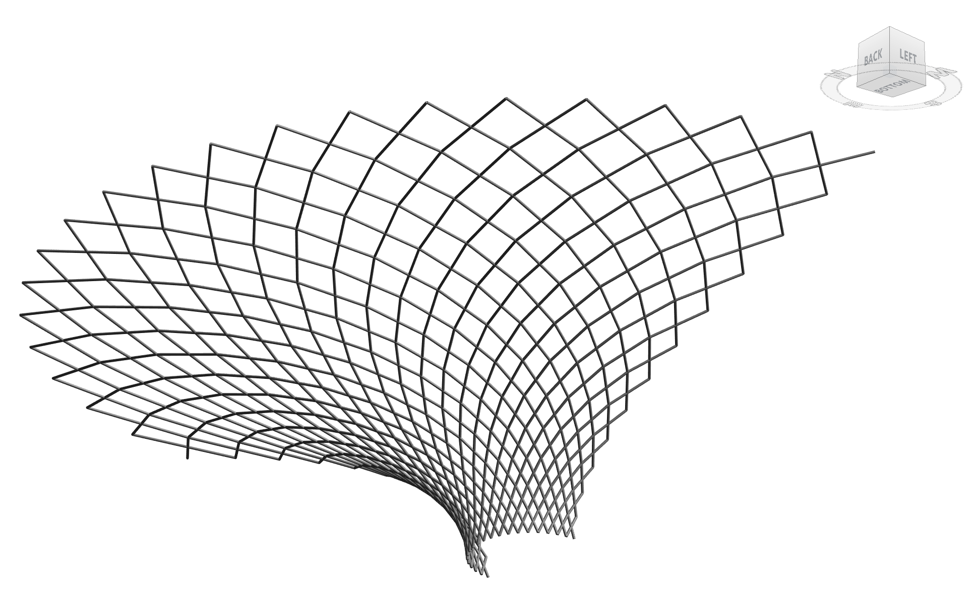
The Design Intent Win
Is this a perfect model of King’s Cross? No. The real structure features complex tapered beams, custom-fabricated nodes, and varying steel depths that a 50-line script naturally simplifies, however, the results are undeniably impressive.
With nothing more than a vague, two-sentence prompt, the AI was able to decipher the design intent of a world-class architectural landmark by understanding the diagrid logic, the funnel geometry, and the structural flow. It then translated that knowledge into a native Revit model by generating raw C# for a macro.
I’ll let you decide. Does this prove that AI is becoming a powerful partner for rapid architectural prototyping and generating complex geometry in Revit?
Closing Thoughts
I want to be clear: this macro creates a geometric approximation, not a structural solution. The actual King’s Cross roof is a masterpiece of load-flow analysis, fabrication detailing, and heritage preservation.
This code is a sketch… a digital exercise. The intent is to demonstrate that the barrier to entry for complex modeling in Revit is lowering every day.
I don’t think you need to be a coding wizard anymore; you just need to be a curious designer with a good prompt.
What will you build today?